Twin Post System

2 in P / 3 in P / 4 in L

A robust ground-mounted solar PV system available in 2 in Portrait and 3 in Portrait configurations, combining balanced structural support with project-specific engineering and flexible UK manufacturing.

Overview

The HTR Solar Twin-Post Fixed-Tilt System is designed for ground-mounted solar PV projects requiring a strong, stable and practical structural arrangement.

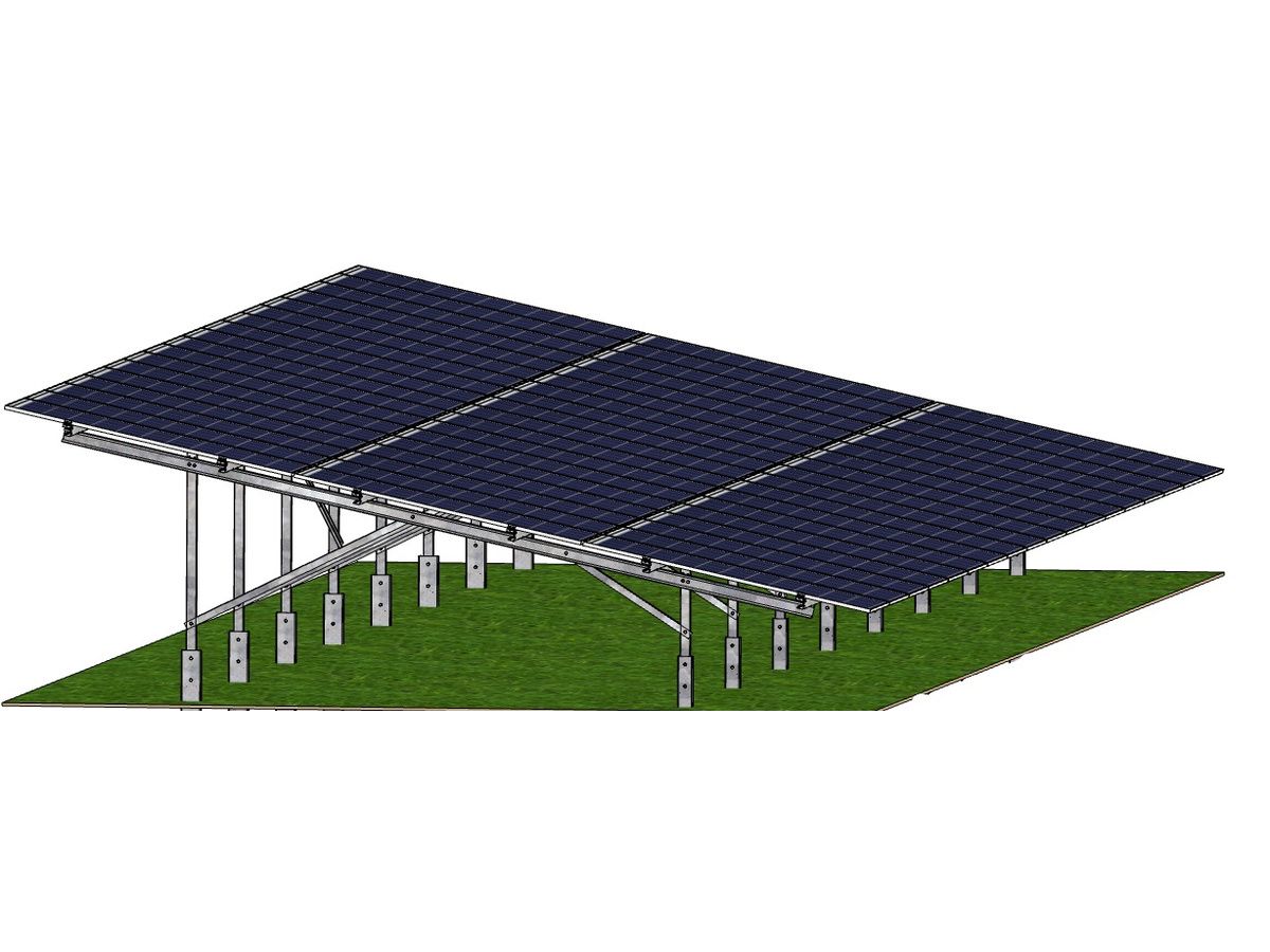
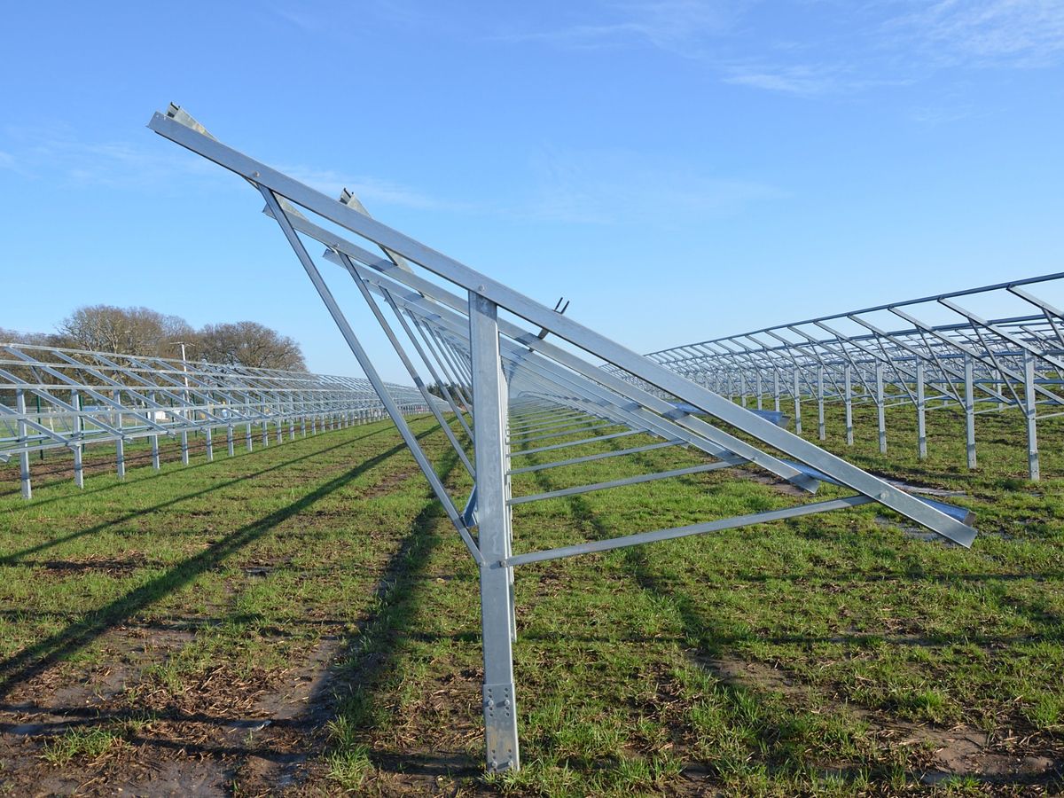
Available in 2 in Portrait (2P) and 3 in Portrait (3P) configurations, the system uses front and rear foundation posts to support the inclined module table. This arrangement distributes the structural actions between two support lines and provides a stable base for the supporting rafters and stringers.

The twin-post arrangement provides effective resistance to vertical, lateral and uplift actions while helping control frame movement and rafter deflection. It is particularly suited to module arrangements requiring reliable support across the table slope.

Our engineers consider module dimensions, table geometry, tilt angle, wind and snow actions, topography, ground conditions, corrosion environment and required design life when developing the final mounting arrangement.

By combining in-house structural engineering with flexible UK manufacturing, we can coordinate the posts, rafters, stringers, connections and foundation interfaces as one complete project-specific solution.
Configurations
  • S5.1 | S5.2
Discuss Your Project
2 in P / 3 in P / 4 in L

Why Choose Our 2 in P Fixed Tilt Solar Mounting System?

  • Balanced Load Distribution

    Front and rear posts distribute the structural actions between two foundation lines, helping manage the compression, uplift and lateral reactions transferred into the ground.

  • Increased Structural Stability

    The wider support arrangement provides a stable structural base and effective resistance to wind, snow, uplift and lateral loading.

  • Effective Rafter Support

    Supporting the rafter at front and rear locations helps control bending and deflection across the table slope, maintaining the required structural performance.

  • Suitable for 2P and 3P Configurations

    The system provides effective support across the module table, making it suitable for both 2 in Portrait and 3 in Portrait arrangements.

  • Practical Installation

    The clearly defined front and rear support lines assist with setting out, frame alignment and repeatable assembly across the solar array.

  • Project-Specific Engineering

    The posts, rafters, stringers, bracing and connections are engineered together around the selected PV modules, applicable structural actions, ground conditions and required design life.

Technical Specifications

Technical Specifications for 2 in P / 3 in P / 4 in L
ParameterTypical Specification
System TypeFixed-tilt ground-mounted PV mounting system
System Configuration2 in Portrait (2P) and 3 in Portrait (3P)
Mounting typeFixed-tilt ground-mounted solar PV system
Primary support arrangementTwin post – front and rear supports
Module orientationPortrait
Table LengthProject-specific
Table lengthProject-specific
Module compatibilityDesigned around the selected PV module dimensions and approved fixing zones
Panel FixingOver-panel or under-panel clamping
Structural designProject-specific design for wind, snow, dead, imposed and other applicable site actions
Structural materialsGalvanised or metallic-coated steel, specified for the project
TopographyDesigned to accommodate the project-specific ground profile
Panel fixingHTR-approved over-panel or under-panel fixing arrangement
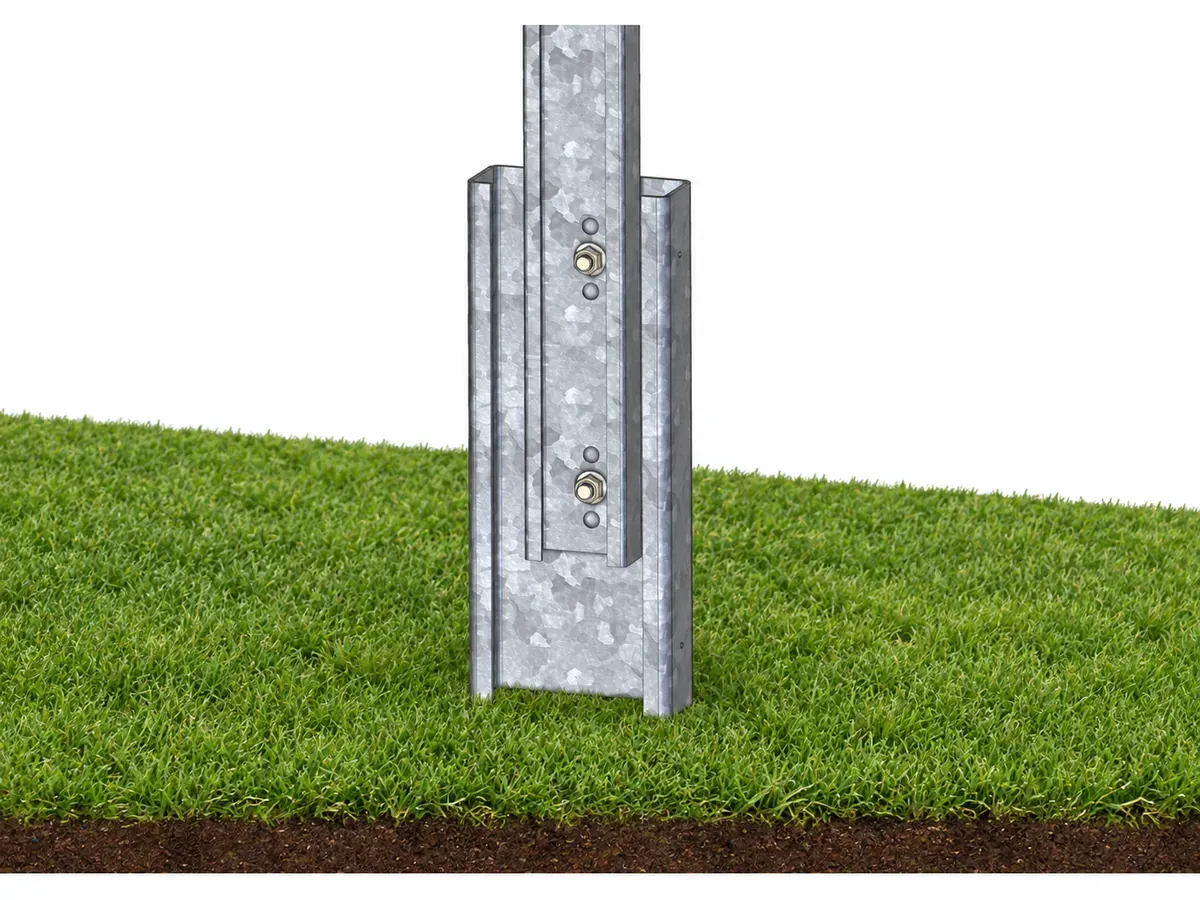
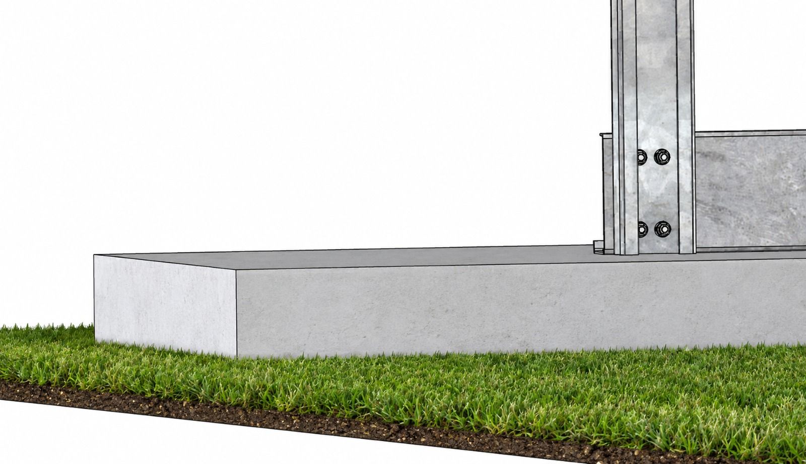
Foundation optionsDriven pile, screw pile, ballast, root anchor, gabion basket or project-specific hybrid solution
TopographyDesigned to accommodate the project-specific ground profile
Corrosion protectionSpecified according to the site environment, ground conditions and required design life
Design lifeProject-specific
ManufacturingUK manufactured using project-specific profiles and connection details

Module Fixing Options

Over-Panel Clamping

PV modules are secured from above using mid-clamps between adjacent modules and end-clamps at the ends of each module row. Clamp locations are coordinated with the module manufacturer’s approved fixing zones.

Under-Panel Clamping

Where specified, modules can be secured from beneath the frame using a compatible under-panel fixing arrangement. This provides an alternative installation method while maintaining the required fixing positions and structural performance.

Planning a Site That Needs This?

Share your ground conditions and layout and we'll engineer the mounting solution around them.

Get in Touch