Spirafix Screw Piles

Foundation Solution

An impact-driven foundation solution for ground-mounted solar PV systems where conventional driven piles may not be suitable or may not achieve the required project-specific uplift resistance.

Overview

Spirafix screw piles, provide an alternative foundation solution for ground-mounted solar PV systems where conventional driven piles are restricted by ground conditions, shallow refusal, limited achievable embedment or insufficient uplift resistance.

They can be considered where a ballasted or gabion foundation is not preferred and a secure, ground-anchored solution is required.

Spirafix screw piles are installed by impact driving. As each anchor is driven into the ground, its helical profile allows it to rotate naturally and develop a secure connection with the surrounding ground.

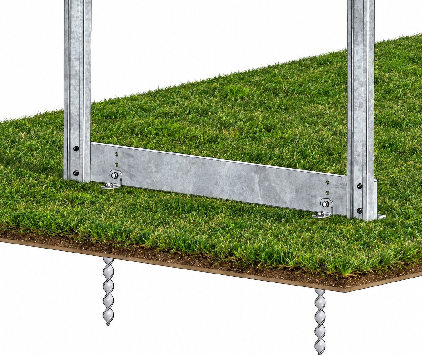
For HTR Solar mounting systems, the Spirafix screw piles  are connected through project-specific brackets to a horizontal foundation member. This horizontal member is then connected to the table uprights, creating a coordinated load path between the solar mounting structure and the ground anchors.

The number, diameter, length and spacing of the Spirafix , together with the horizontal member and bracket connections, are developed according to the table reactions, ground conditions and results of project-specific site testing.
Configurations
  • S5.1 | S5.2
Discuss Your Project
Spirafix Screw Piles

Why Choose Spirafix screw piles

  • Alternative Where Driven Piles Are Unsuitable

    A project-specific foundation option for locations affected by shallow refusal, restricted pile embedment, difficult drivability or insufficient driven-pile resistance.

  • Enhanced Uplift Solution

    Spirafix can provide uplift resistance where driven piles are unsuitable. Capacity depends on anchor size, embedment and ground conditions, confirmed through site-specific testing

  • Impact-Driven Installation

    The Spirafix screw piles are installed using impact-driving equipment. Their helical profile allows them to rotate naturally into the ground with each impact

  • Integrated Structural Arrangement

    Project-specific brackets connect Spirafix to a horizontal foundation member, which then connects to the table uprights, linking the foundation and mounting structure.

  • Removable Solution

    Where required, Spirafix screw piles can be counter-rotated and removed, making the system suitable for permanent, temporary and semi-permanent applications.

  • Project-Specific Engineering and Testing

    Spirafix size, length, spacing and connection details are selected around the structural reactions, ground conditions and verified site-test results.

Frame Specification

Frame Specification for Spirafix Screw Piles
ParameterTypical Specification
Foundation typeImpact-driven Spirafix
Installation methodImpact driven with natural rotation during installation
Spirafix quantity and arrangementDetermined by project-specific structural design
Spirafix position and spacingDefined according to table reactions, horizontal-member design and ground conditions
Primary design actionProject-specific uplift or tensile resistance
Spirafix -to-member connectionProject-specific bracket arrangement
Foundation memberHorizontal structural member connecting the Spirafix brackets to the table uprights
Upright connectionProject-specific connection between the horizontal member and mounting-system uprights
Removal methodCounter-rotation
Site suitabilitySubject to project-specific ground conditions, structural requirements and testing
Mounting-system compatibilityHTR Solar ground-mounted PV mounting systems

Module Fixing Options

Site Conditions and Foundation Design

Ground conditions can vary considerably across a solar site. Spirafix selection must therefore be based on project-specific ground conditions and structural reactions rather than standard published capacities alone. Where conventional driven piles encounter shallow refusal, restricted embedment or insufficient uplift resistance, a Spirafix arrangement can be assessed as an alternative foundation solution. Site testing is undertaken where required to determine the achievable anchor capacity in the actual ground conditions. The results are then assessed against the structural reactions from the solar mounting table. The foundation design considers: •Maximum uplift or tensile reaction •Spirafix diameter and length •Number of Spirafix required at each foundation position •Spirafix spacing and orientation •Ground conditions and achievable installation depth •Horizontal foundation-member design •Spirafix bracket and upright connections •Installation tolerances •Project-specific testing requirements Spirafix may provide greater achievable uplift resistance than a conventional driven pile where the driven pile is restricted by ground conditions or available embedment. However, the relative performance must be established through project-specific engineering and site testing.

Spirafix Installation and Site Support

Spirafix screw piles are installed by impact driving rather than rotational installation. A suitably sized hammer cap or machine adapter is placed over the Spirafix head to protect the connection during installation. Impact-driving equipment is then used to advance the anchor into the ground. The helical profile causes the anchor to rotate naturally with each impact. For larger Spirafix or solar projects requiring multiple foundation positions, installation may be completed using an excavator-mounted breaker or specialist installation equipment. Following Spirafix installation: •The Spirafix positions, alignment and installation depths are checked. •Project-specific brackets are connected to the installed Spirafix . •The horizontal foundation member is secured to the Spirafix brackets. •The table uprights are connected to the horizontal member. •The above-ground mounting structure is assembled from the uprights. •Where specified, proof or verification testing is undertaken to confirm the required foundation performance. HTR Solar defines the Spirafix arrangement, horizontal-member details, bracket connections, upright positions and installation tolerances through the project-specific design documentation. Before installation begins, buried services must be identified and the required site-safety procedures followed.

Planning a Site That Needs This?

Share your ground conditions and layout and we'll engineer the mounting solution around them.

Get in Touch